侦侦拍AI相机快速参考
更详细的中文教程请参见: 侦侦拍AI相机官方中文教程-侦侦拍AI相机嵌入式图像处理


通用硬件控制
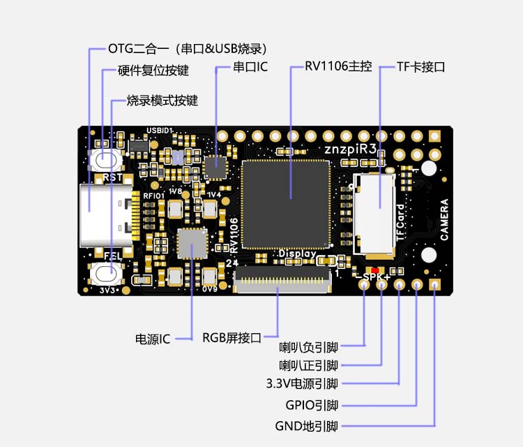
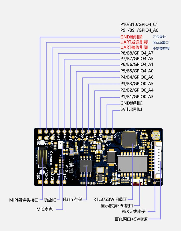
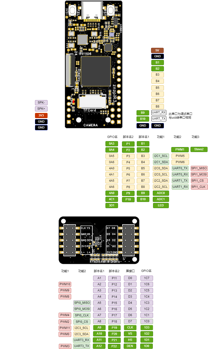
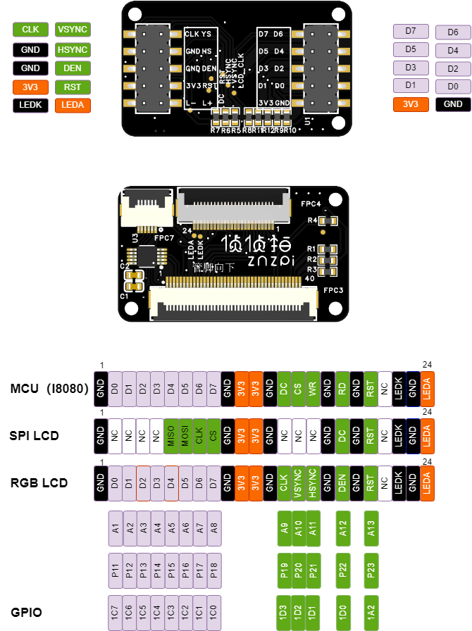
侦侦拍AI相机所有的管脚都能用 machine 模块进行控制。请参考上面图中SPI/I2C/UART/PWM/TIME的具体位置
延时和时间
使用 time 模块
import time

time.sleep(1)           # sleep for 1 second
time.sleep_ms(500)      # sleep for 500 milliseconds
time.sleep_us(10)       # sleep for 10 microseconds
start = time.ticks_ms() # get millisecond counter
delta = time.ticks_diff(time.ticks_ms(), start) # compute time difference
虚拟定时
使用示例
from machine import Timer

tim0 = Timer(-1)
tim0.init(period=5000, mode=Timer.ONE_SHOT, callback=lambda t:print(0))

tim1 = Timer(-1)
tim1.init(period=2000, mode=Timer.PERIODIC, callback=lambda t:print(1))
周期单位为毫秒
引脚和GPIO
参考 machine.Pin class:
from machine import Pin

p0 = Pin('P0', Pin.OUT) # create output pin on GPIO0
p0.on()                 # set pin to "on" (high) level
p0.off()                # set pin to "off" (low) level
p0.value(1)             # set pin to on/high

p2 = Pin('P2', Pin.IN)  # create input pin on GPIO2
print(p2.value())       # get value, 0 or 1

p4 = Pin('P4', Pin.IN, Pin.PULL_UP) # enable internal pull-up resistor
p5 = Pin('P5', Pin.OUT, value=1) # set pin high on creation
有一个更高层级的操作 machine.Signal 来翻转管脚的电平。 对于LED的 控制 on() 或 value(1) 非常有用。
UART串口
详见 machine.UART.
from machine import UART

uart1 = UART(1, baudrate=115200)
uart1.write('hello')  # write 5 bytes
uart1.read(5)         # read up to 5 bytes
ADC 数模转换
使用 machine.ADC class:
from machine import ADC

adc = ADC("P5")          # create ADC object on ADC pin
adc.read_u16()              # read value, 0-65536 across voltage range 0.0v - 3.3v
ADC的分辨率是10bit精度,如果需要更高精度需要使用外接ADC
硬件SPI总线
硬件SPI总线通过 machine.SPI class 使用,方法与软SPI总线相同
from machine import SPI, Pin

spi = SPI(1, 10000000)
cs_pin = Pin(6, Pin.OUT, value=1)
cs_pin(0)
spi.write('Hello World')
cs_pin(1)
cs选项用来使能,0或1,默认为-1,表示自动。
提示
即使硬件支持最高30MH波特率,但会由一定的误差,特别是在较高的波特率的情况下。
可以是指比较高的波特率。最高可以以60MHz接收,90MHz发送。
硬件I2C
硬件I2C通过 machine.I2C 使用方法与软I2C相同。
from machine import I2C

i2c = I2C(1, 400_000)
i2c.writeto(0x76, b"Hello World")
实时时钟(RTC)
详见 machine.RTC:
from machine import RTC

rtc = RTC()
rtc.datetime((2017, 8, 23, 1, 12, 48, 0, 0)) # set a specific date and time
rtc.datetime() # get date and time
rtc.now() # return date and time in CPython format.
基于瑞芯微RV1106的侦侦拍AI相机的通用板控制
侦侦拍AI相机通过 pyb 模块控制相机的硬件。 pyb 将被废弃。请使用 machine
延时和时间
详见 time module:
import utime

utime.sleep(1)           # sleep for 1 second
utime.sleep_ms(500)      # sleep for 500 milliseconds
utime.sleep_us(10)       # sleep for 10 microseconds
start = utime.ticks_ms() # get value of millisecond counter
delta = utime.ticks_diff(utime.ticks_ms(), start) # compute time difference
发光二极管
详见 pyb.LED.
from pyb import LED

led = LED(1) # red led
led.toggle()
led.on()
led.off()
LED管脚
LED(1) -> Red RGB LED Segment
LED(4) -> IR LEDs
引脚和GPIO
详见 pyb.Pin.
from pyb import Pin

p_out = Pin('P7', Pin.OUT_PP)
p_out.high()
p_out.low()

p_in = Pin('P8', Pin.IN, Pin.PULL_UP)
p_in.value() # get value, 0 or 1
GPIO控制
Pin(‘P1’) -> P1 (GPIO_0A3)
Pin(‘P2’) -> P2 (GPIO_0A4)
Pin(‘P3’) -> P3 (GPIO_0A5)
Pin(‘P4’) -> P4 (GPIO_4A6)
Pin(‘P5’) -> P5 (GPIO_4A0)
Pin(‘P6’) -> P6 (GPIO_4A1)
Pin(‘P7’) -> P7 (GPIO_4A5)
Pin(‘P8’) -> P8 (GPIO_4A6)
Pin(‘P9’) -> P9 (GPIO_4A0)
只支持3.3V电压
所有管脚支持25mA电流
舵机控制
详见 pyb.Servo.
from pyb import Servo

s1 = Servo(1) # servo on position 1 (P7)
s1.angle(45) # move to 45 degrees
s1.angle(-60, 1500) # move to -60 degrees in 1500ms
s1.speed(50) # for continuous rotation servos
舵机管脚
Servo(2) -> P2 (GPIO_0A4)
外触发中断
详见 pyb.ExtInt.
from pyb import Pin, ExtInt

callback = lambda e: print("intr")
ext = ExtInt(Pin('P7'), ExtInt.IRQ_RISING, Pin.PULL_NONE, callback)
GPIO控制
Pin(‘P1’) -> P1 (GPIO_0A3)
Pin(‘P2’) -> P2 (GPIO_0A4)
Pin(‘P3’) -> P3 (GPIO_0A5)
Pin(‘P4’) -> P4 (GPIO_4A6)
Pin(‘P5’) -> P5 (GPIO_4A0)
Pin(‘P6’) -> P6 (GPIO_4A1)
Pin(‘P7’) -> P7 (GPIO_4A5)
Pin(‘P8’) -> P8 (GPIO_4A6)
Pin(‘P9’) -> P9 (GPIO_4A0)
定时器
详见 pyb.Timer.
from pyb import Timer

tim = Timer(2, freq=1000)
tim.counter() # get counter value
tim.freq(0.5) # 0.5 Hz
tim.callback(lambda t: pyb.LED(1).toggle())
For znzpi Cam M4: TIM2, TIM3, and TIM4
For znzpi Cam F7: TIM2, TIM3, TIM4 and TIM7 through TIM14
For znzpi Cam H7: TIM2, TIM3, TIM4, TIM7, TIM8 and TIM12 through TIM17
PWM (pulse width modulation)
from pyb import Pin, Timer

p = Pin('P4') # P4 has TIM2, CH3
tim = Timer(2, freq=1000)
ch = tim.channel(3, Timer.PWM, pin=p)
ch.pulse_width_percent(50)
ADC 数模转换
from pyb import Pin, ADC

adc = ADC(Pin('P6'))
adc.read() # read value, 0-4095
ADC管脚
ADC(Pin(‘P10’)) -> P6 (GPIO_4C1)
P6 is 3.3V tolerant in ADC mode - NOT 5V TOLERANT!
DAC(数模转换)
from pyb import Pin, DAC

dac = DAC('P6')
dac.write(120) # output between 0 and 255
DAC管脚
DAC(Pin(‘P3’)) -> P3 (GPIO_0A5)
P6 is 3.3V tolerant in DAC mode - NOT 5V TOLERANT!
UART串口
详见 pyb.UART.
from pyb import UART

uart = UART(3, 9600, timeout_char=1000)
uart.write('hello')
uart.read(5) # read up to 5 bytes
UART 管脚
UART 0 RX -> P5 (GPIO_4A0)
UART 0 TX -> P6 (GPIO_4A1)
UART 1 RX -> P7 (GPIO_4A5)
UART 1 TX -> P8 (GPIO_4A6)
SPI总线
详见 pyb.SPI.
from pyb import SPI

spi = SPI(1, SPI.MASTER, baudrate=1000000, polarity=1, phase=0)
spi.send('hello')
spi.recv(5) # receive 5 bytes on the bus
spi.send_recv('hello') # send a receive 5 bytes
SPI管脚
SPI 1 MOSI (Master-Out-Slave-In) -> P5 (GPIO_4A0)
SPI 1 MISO (Master-In-Slave-Out) -> P6 (GPIO_4A1)
SPI 1 SS (Serial Select) -> P7 (GPIO_4A5)
SPI 1 SCLK (Serial Clock) -> P8 (GPIO_4A6)
I2C总线
详见 pyb.I2C.
from pyb import I2C

i2c = I2C(2, I2C.MASTER, baudrate=100000)
i2c.scan() # returns list of slave addresses
i2c.send('hello', 0x42) # send 5 bytes to slave with address 0x42
i2c.recv(5, 0x42) # receive 5 bytes from slave
i2c.mem_read(2, 0x42, 0x10) # read 2 bytes from slave 0x42, slave memory 0x10
i2c.mem_write('xy', 0x42, 0x10) # write 2 bytes to slave 0x42, slave memory 0x10
I2C管脚
I2C 0 SCL (Serial Clock) -> P5 (GPIO_4A0)
I2C 0 SDA (Serial Data) -> P6 (GPIO_4A1)
I2C 1 SCL (Serial Clock) -> P3 (GPIO_0A5)
I2C 1 SDA (Serial Data) -> P4 (GPIO_0A6)
I2C 2 SCL (Serial Clock) -> P7 (GPIO_4A5)
I2C 2 SDA (Serial Data) -> P8 (GPIO_4A6)